Remote lights switch
Post ReplyRemote lights switchPosted: Sunday, February 10, 2019 [21:59:28] - 1
While remote lights switches available in many shapes and forms here is another solution. Using RPi Zero W to control micro servo to flip the switch physically. 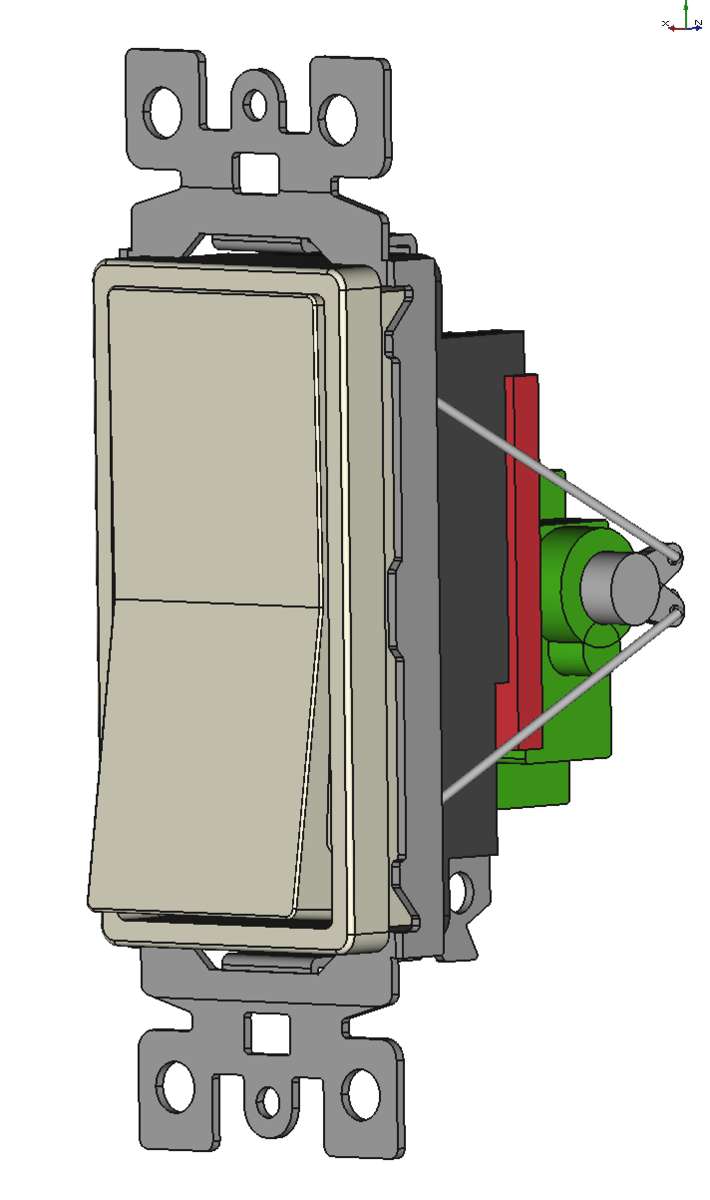 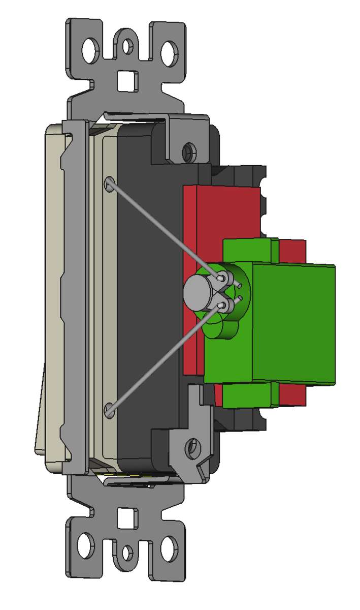 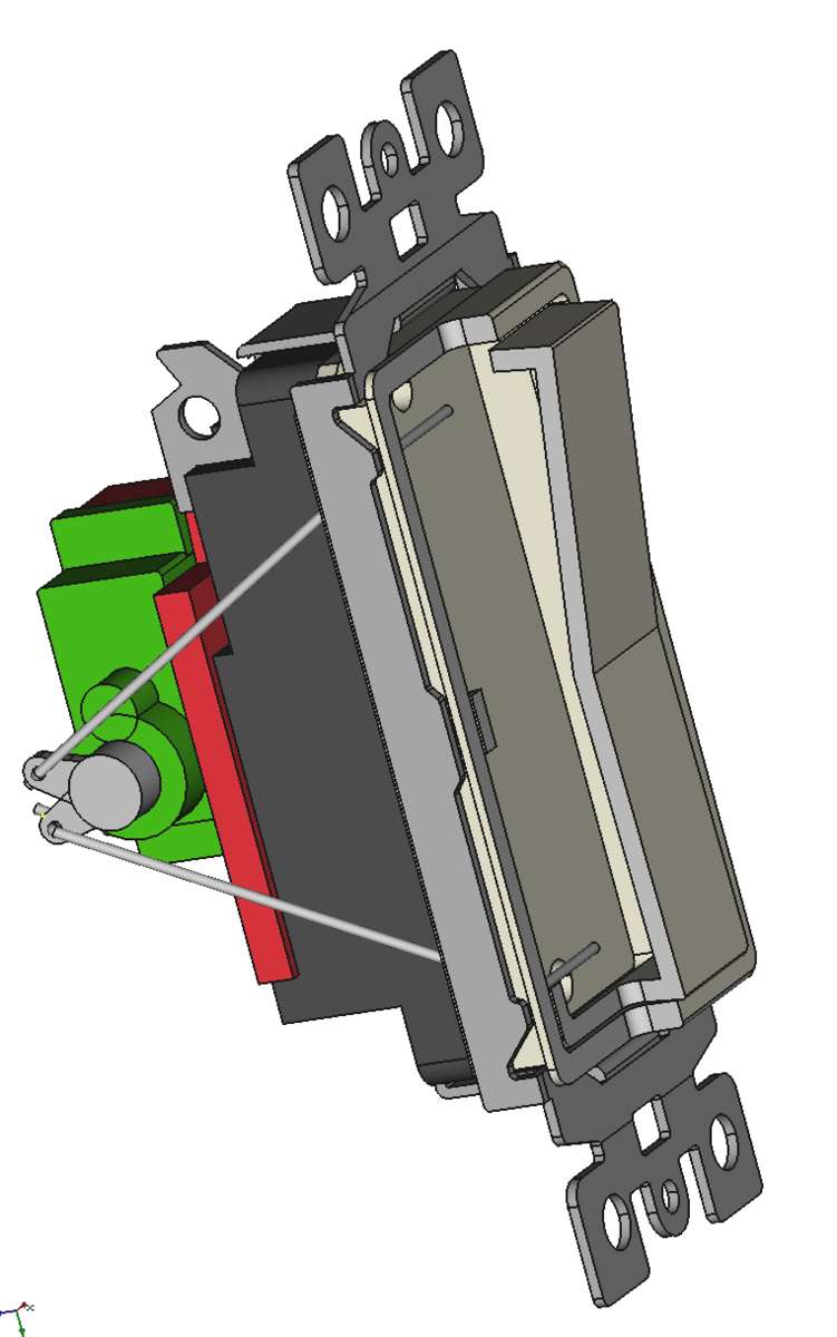 Still working on a part that will report the state of the switch. Switch used in this project is $2 Leviton decora model S11-5601-2IS available in Home Depot. |
 Posted by:
Servo plate for this projectPosted: Sunday, February 10, 2019 [22:06:05] - 2
testing actual switchPosted: Tuesday, February 12, 2019 [00:31:32] - 3
Actually testing switch with servo and manually. 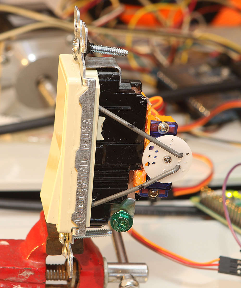 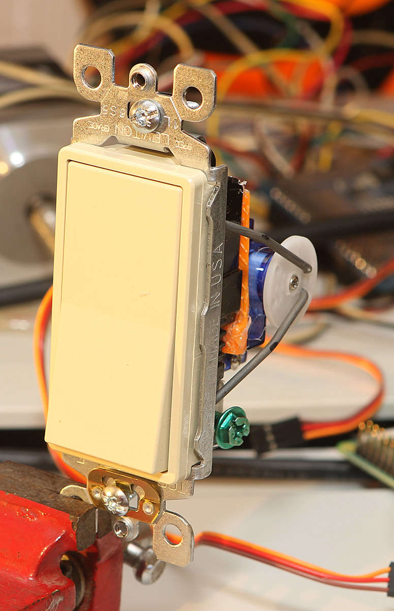 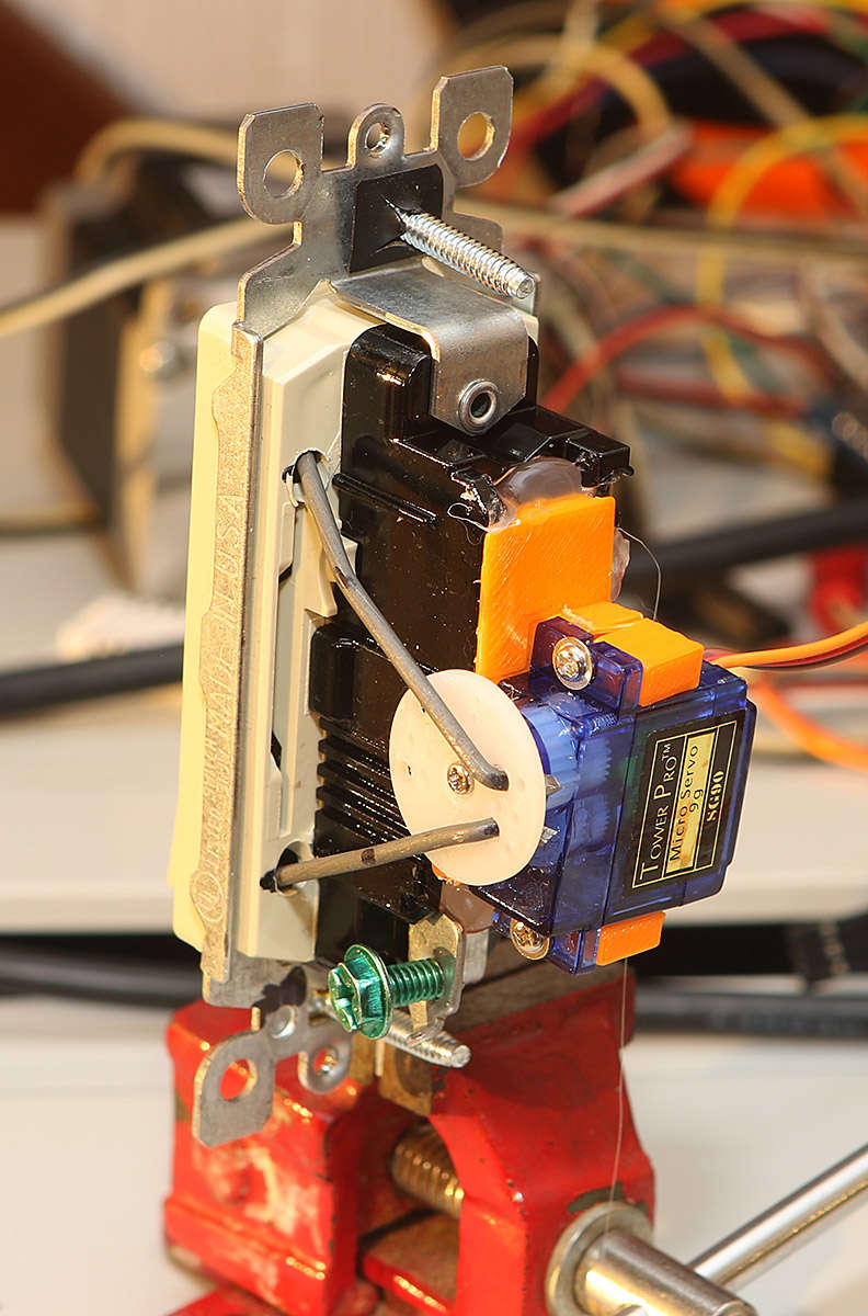 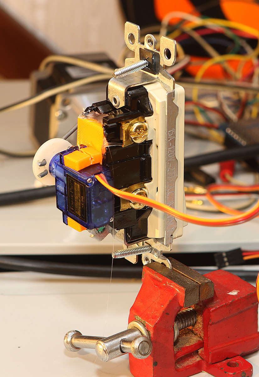 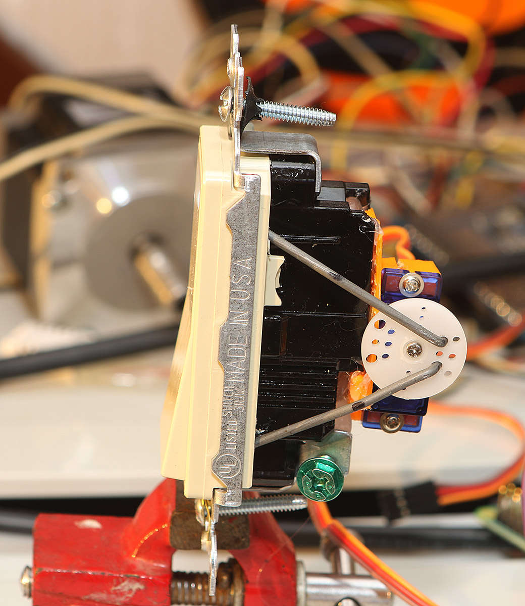 and it works |
RE: Remote lights switchPosted: Friday, March 15, 2019 [13:50:05] - 4
Version 2 of the switch with with position reporting VIA MQTT and registering it in Node-Red Dashboard.
Video do not show indicator color change, so we added screen recording on laptop, that is not exactly synchronized but it gives an idea. Did not work-out switch change on a dashboard, but indication works. 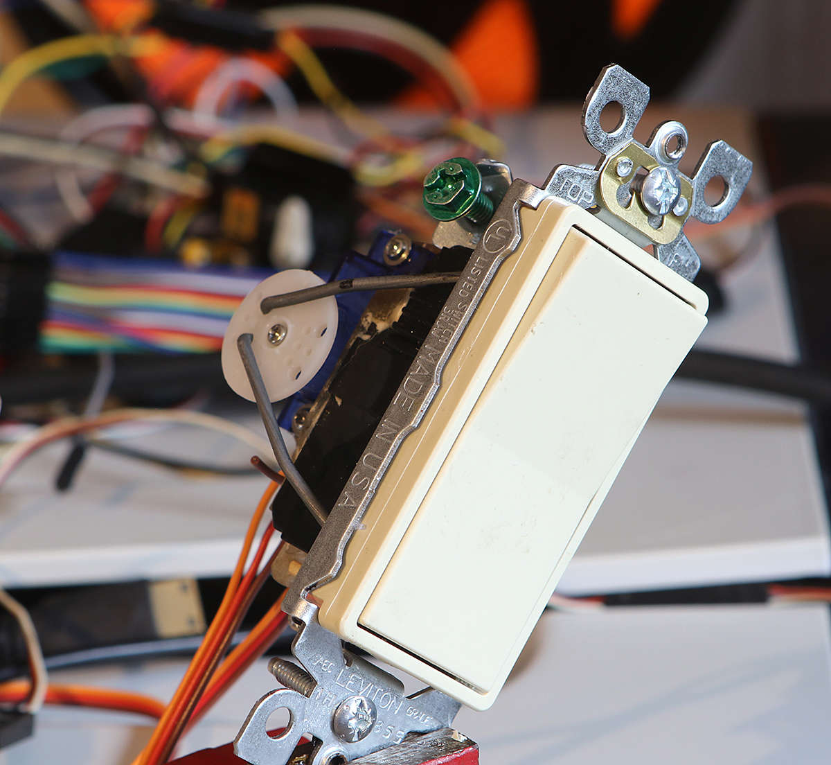  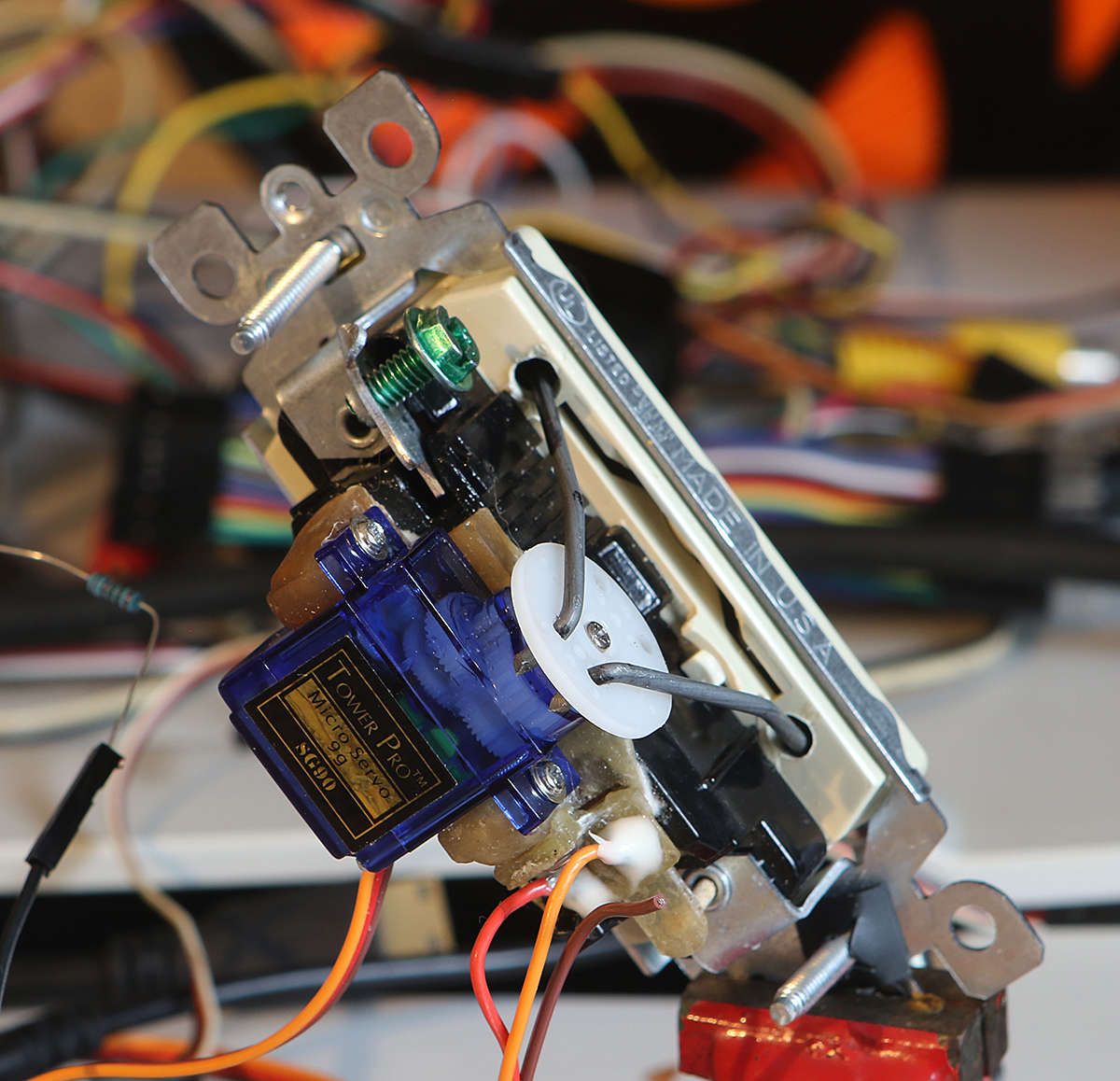 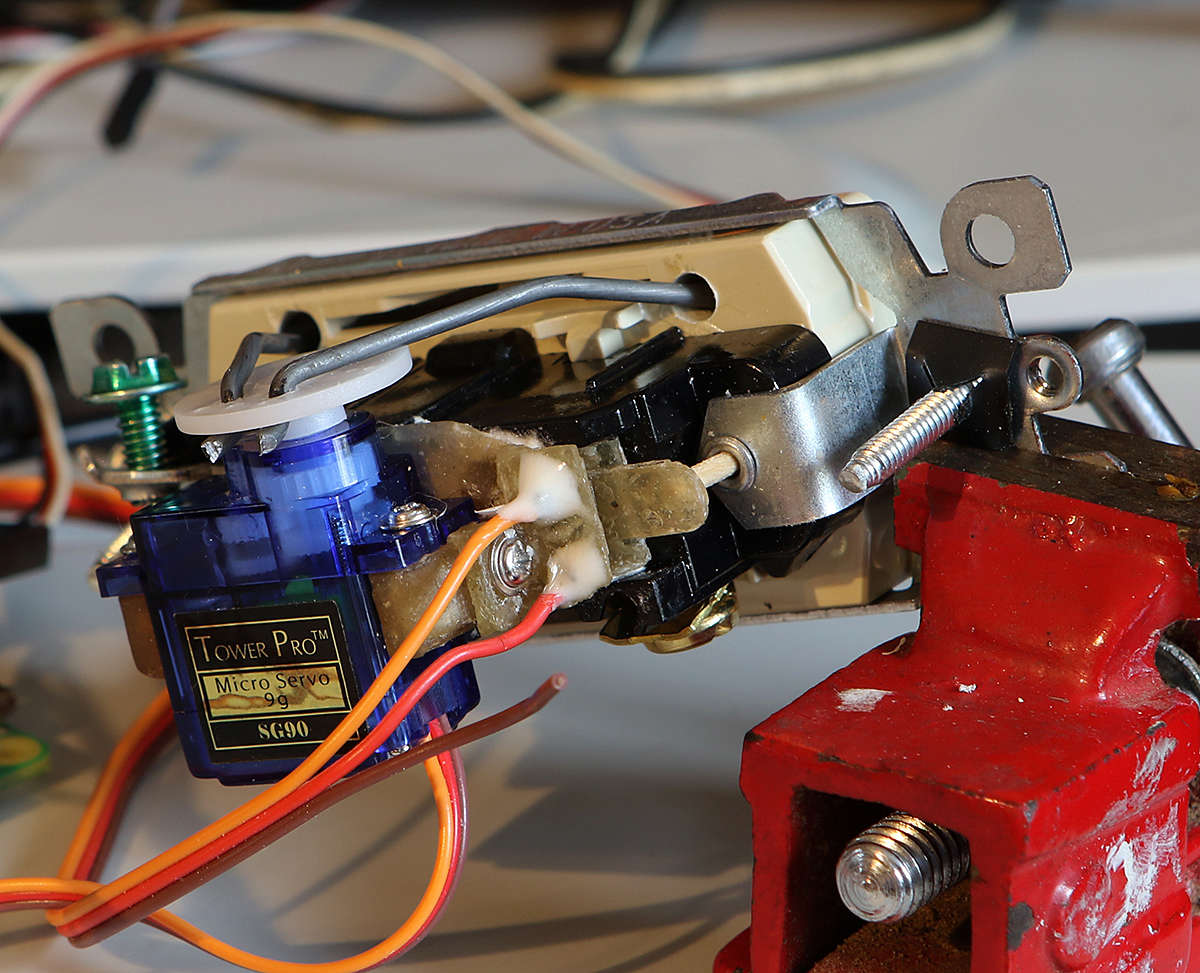 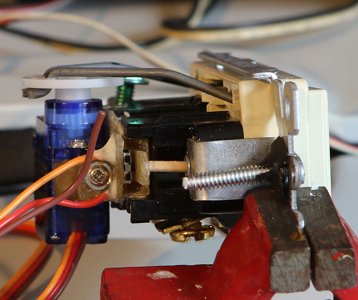 Programming: Node-Red schematics  To be able to pack switch with indicator on one line switch uses 4x1 size and indicator 2x1 (see image below).  based on a input we trigger on or off SSH connection. 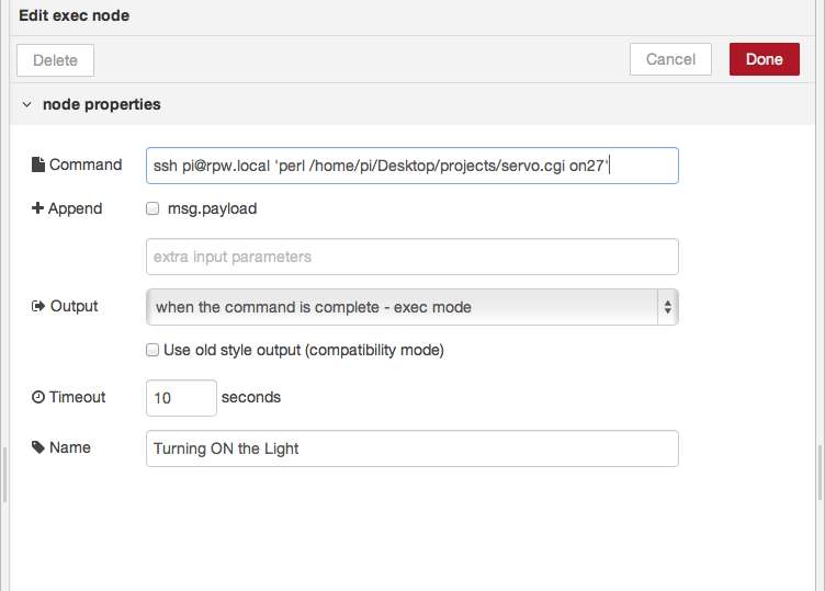 Switch triggers an passwordless SSH connection to RPi to actuate servo. Switch position indicator starts with MQTT in node 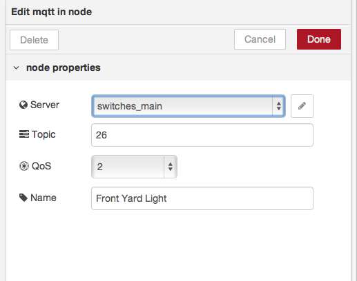 Then it passes data to a function node, where we issue indicator color based on the input with : return msg; then template node creates custom LED indicator based on msg.color  Template: #circle1 { stroke: none; fill: {{msg.color}}; } </style> <svg> <circle id="circle1" cx="10" cy="20" r="10"/> </svg> MQTT client to report switch position: #!/usr/bin/python import paho.mqtt.client as mqttClient import RPi.GPIO as GPIO import time bpin = 26 def on_connect(client, userdata, flags, rc): if rc == 0: print("Connected to broker") global Connected #Use global variable Connected = True #Signal connection else: print("Connection failed") Connected = False broker_address="RPI_IP_ADDRESS" port=1883 client = mqttClient.Client("switches_main") client.on_connect=on_connect client.connect(broker_address, port=port) client.loop_start() while Connected != True: #Wait for connection time.sleep(0.1) GPIO.setmode(GPIO.BCM) GPIO.setup(bpin, GPIO.IN, pull_up_down=GPIO.PUD_UP) try: while True: inputValue = GPIO.input(bpin) if (inputValue == False): print(bpin) value = "On" client.publish(str(bpin),value) else : value = "Off" client.publish(str(bpin),value) time.sleep(3) except KeyboardInterrupt: GPIO.cleanup() client.disconnect() client.loop_stop() This is a test code to verify the project. |
Base for Raspberry Pi with Power supplyPosted: Monday, April 1, 2019 [14:55:20] - 5
Just finished case for Raspberry Pi Zero and power supply. Power supply 5V 3A purchased on eBay for $3 delivered. 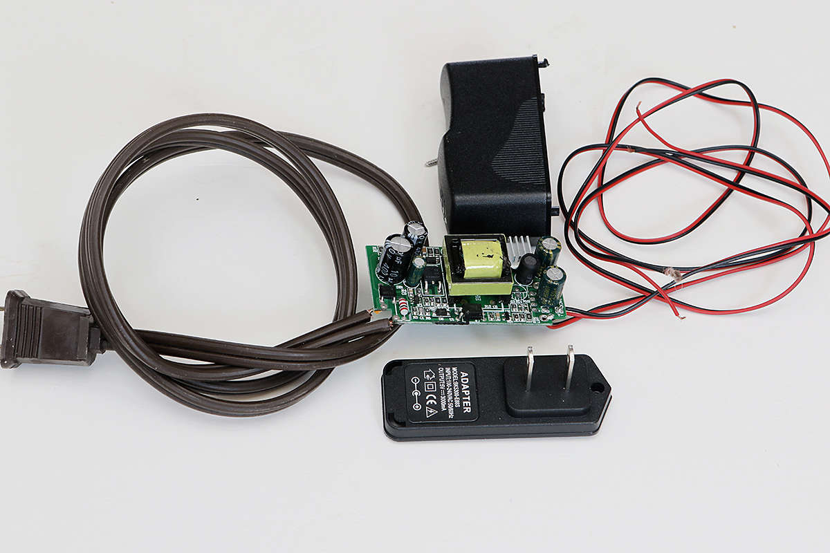 it was removed from the case and power wires were soldered to fit this application. 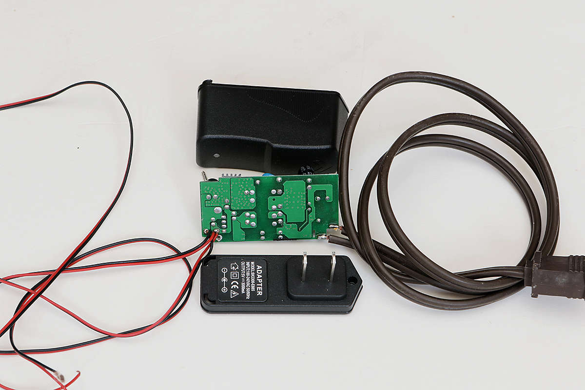 Also a custom header made for easy wiring: 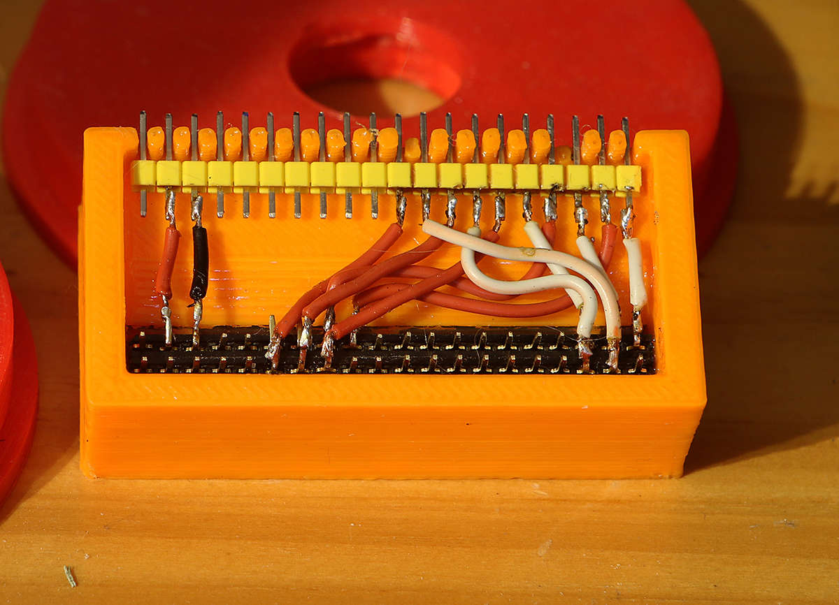 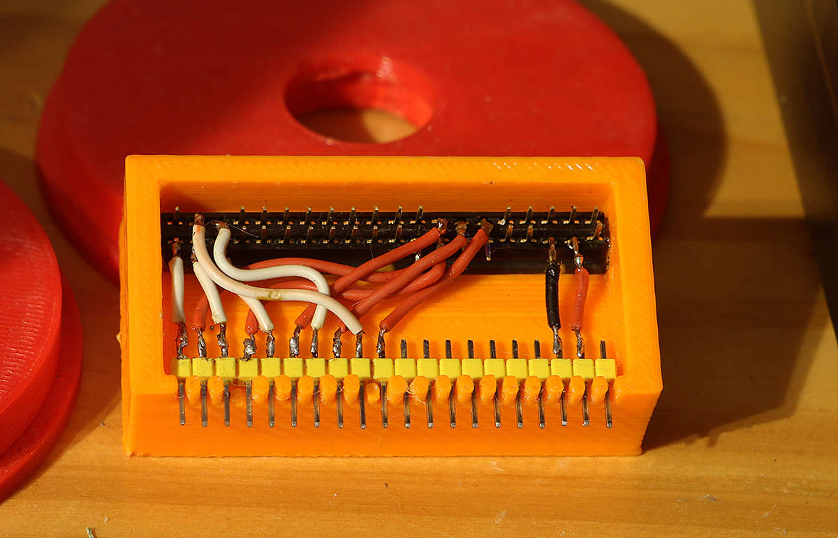 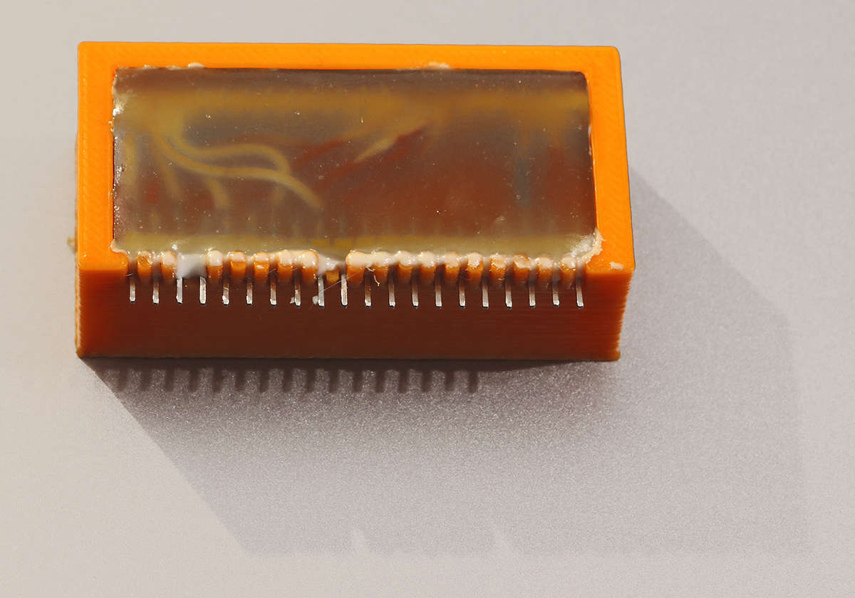 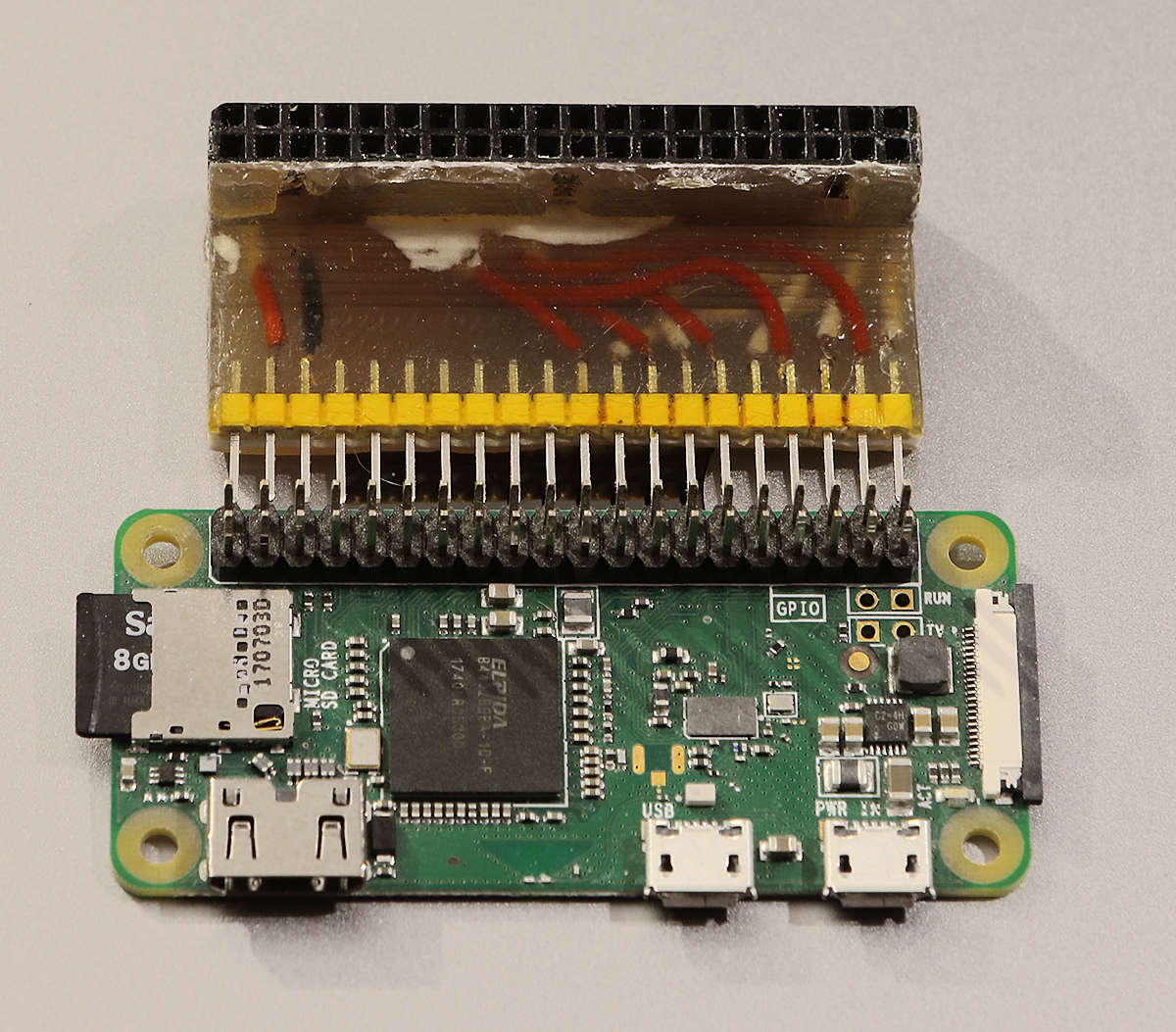 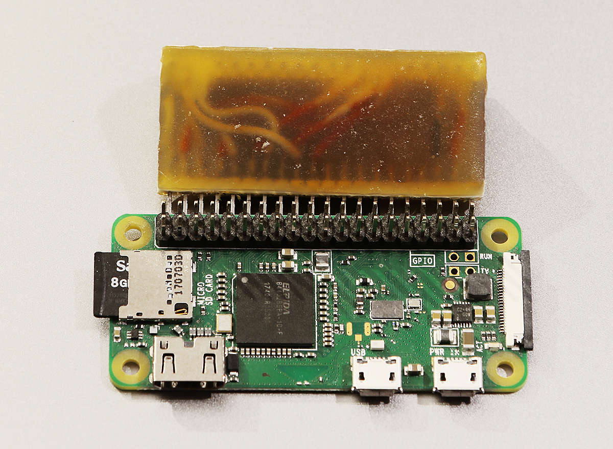 and putting it all together in a case for Raspberry Pi Zero and power supply. Case was 3D printed. 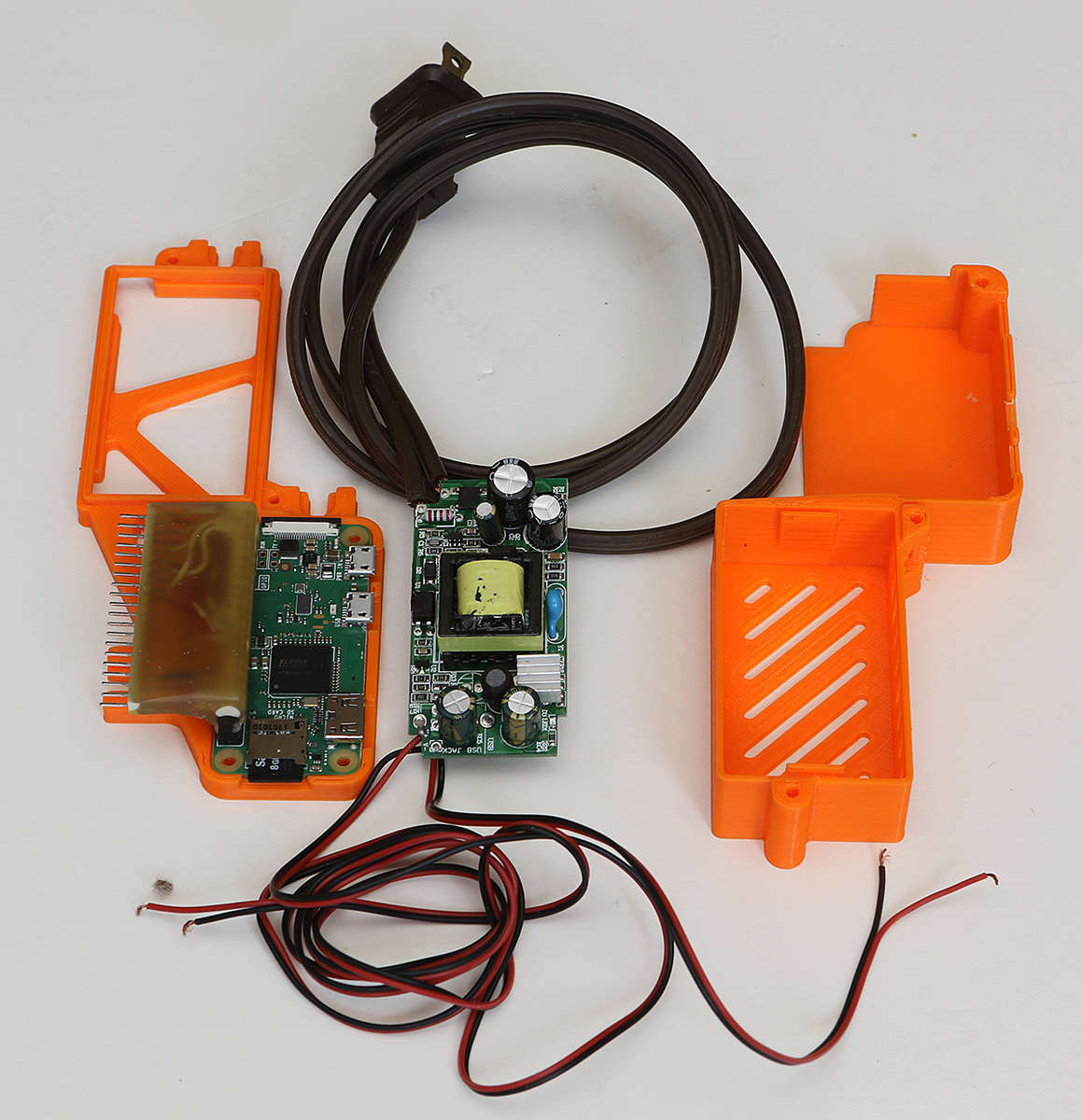  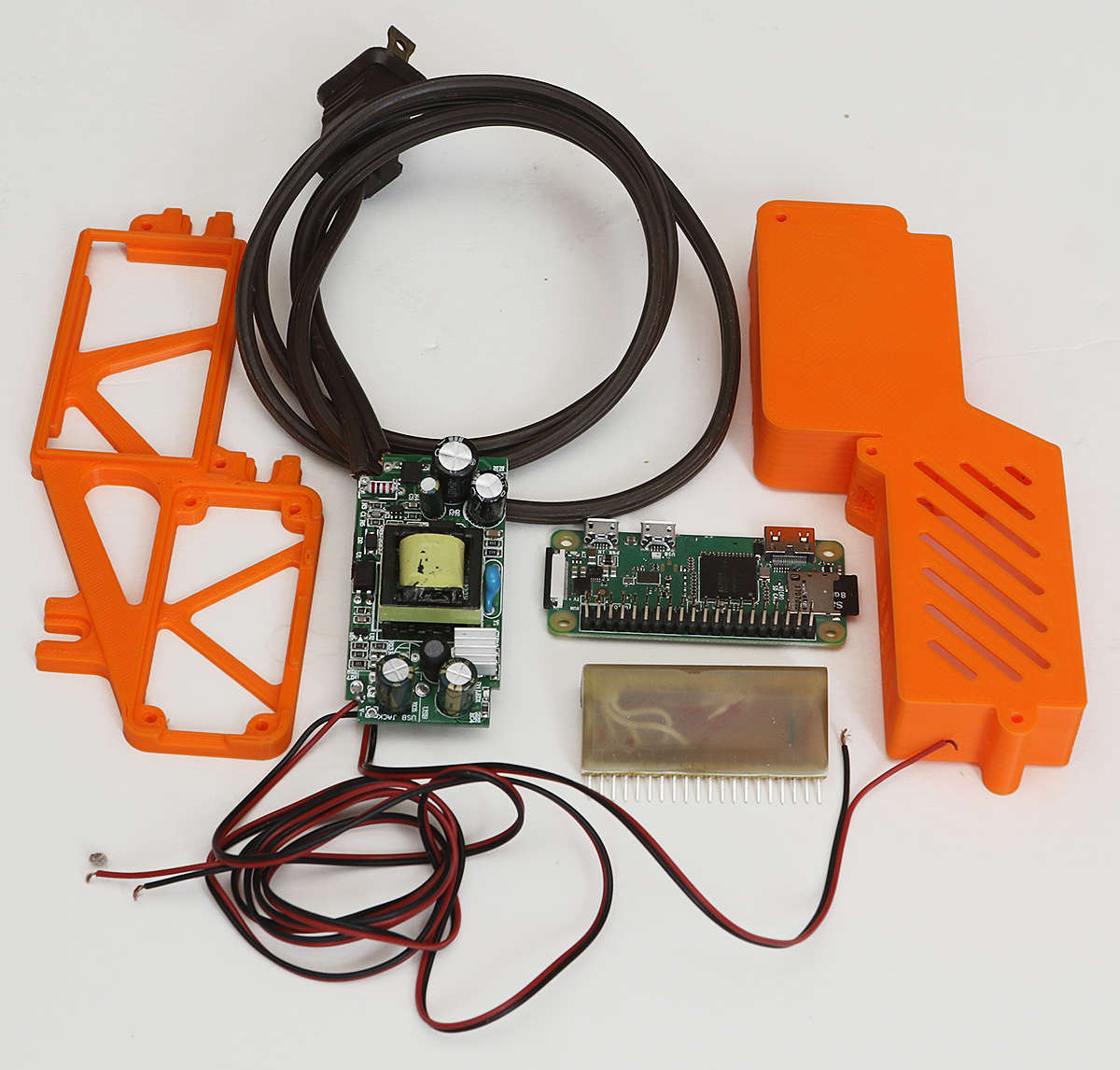 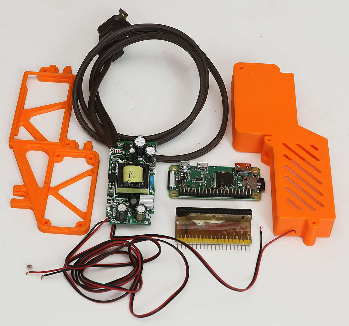 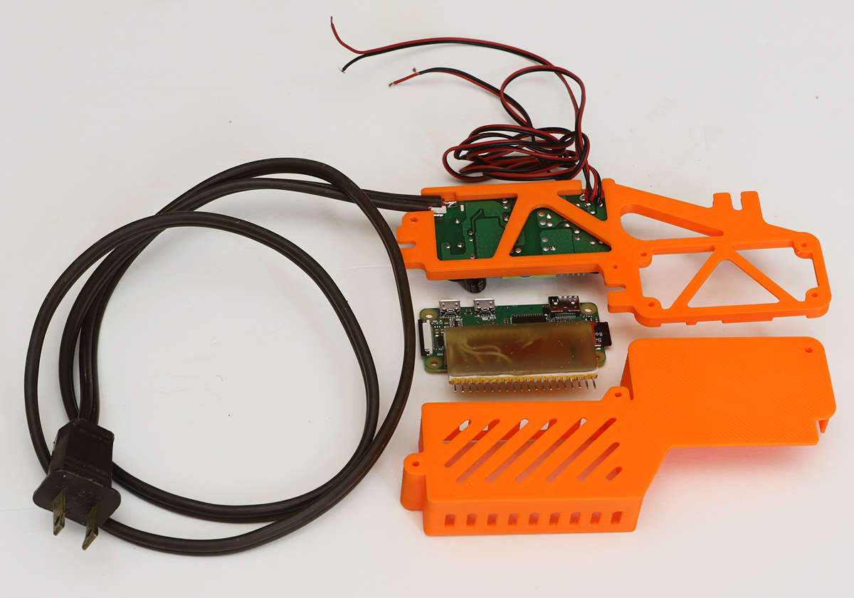 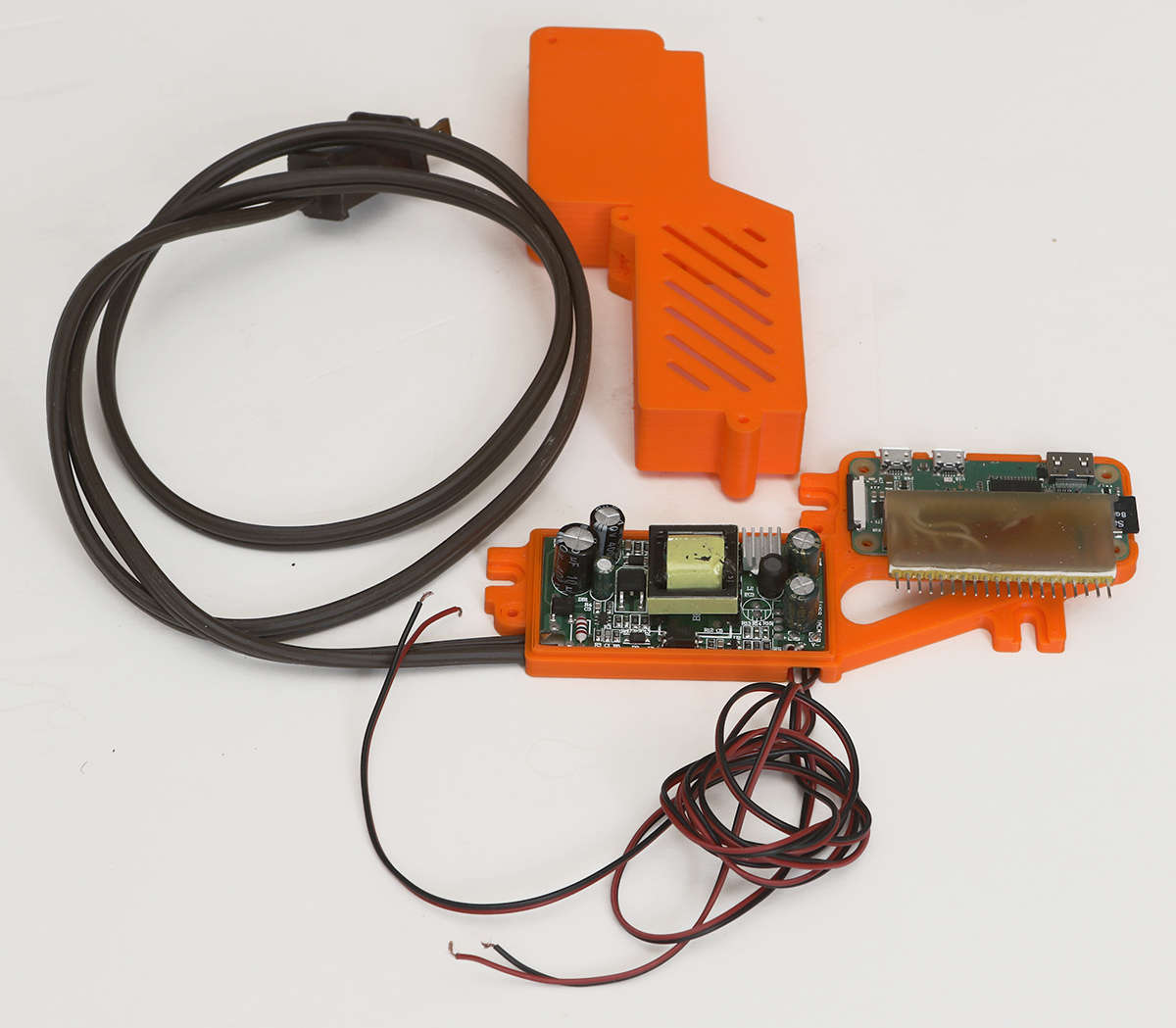  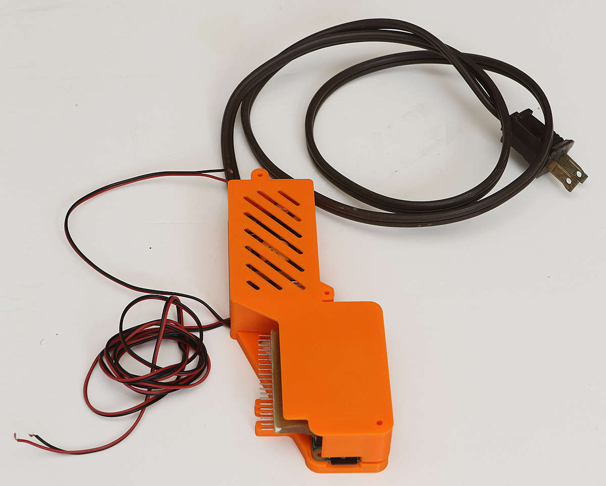  Next is checking all wiring and wall mounting. |
Bench testing complete systemPosted: Friday, April 5, 2019 [23:37:04] - 6
All assembly tested on a bench to make sure all switches work and power supply works as designed.
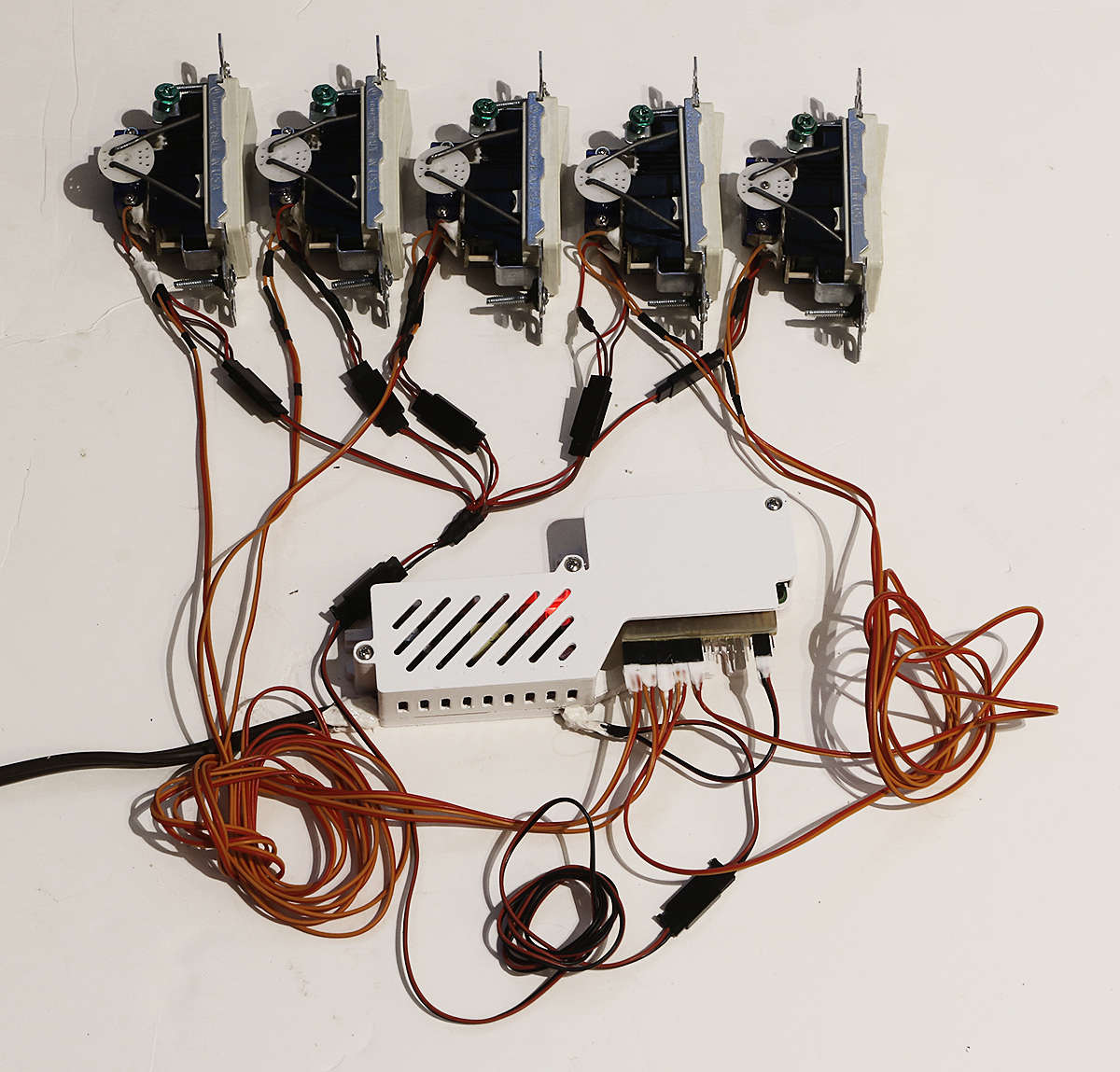 Next, wall installation.. |
Lights switches installedPosted: Monday, April 8, 2019 [16:11:04] - 7
Light switches tested, installed and functioning. Wire connection between switches and Raspberry Pi Zero routed in-wall.
Installation stages:  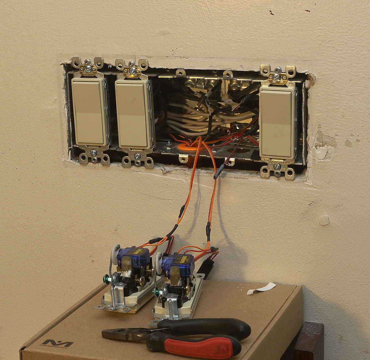 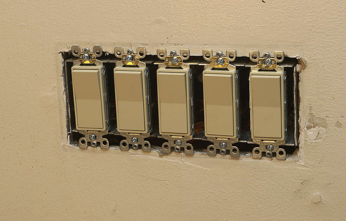 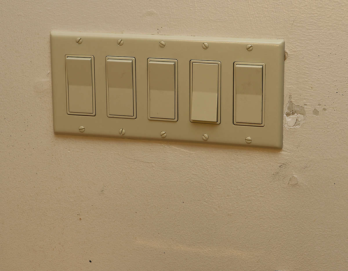 RPi is placed under the lower shelf and not immediately visible. It is powered by BackUPS, so it won't lose the power in case of the power outage. 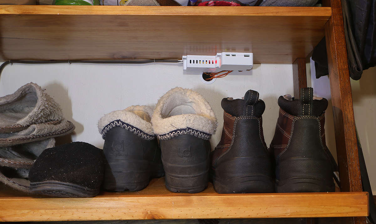 Switch box wiring had to be completely re-done to free-up some space for the enlarged switches. |